Very much WIP; Contact me if your after something specific
Central Locking
There are two possible central locking systems available: single locking and double locking.
Single Locking (4pin lock)
The central locking system with single locking does not require a module. The four-door lock motors M77, M78, M67 and M68) are electrically connected. When one of the front doors is mechanically locked or unlocked, current flows to the three remaining door lock motors and activates them.
DIAGRAM TO BE ADDED
Double type locking (6pin lock)
The single locking process for the four doors functions as described above. The tailgate/decklid motor (M39) can only be activated with double locking.
To activate the double locking system, the key must be turned first to the “unlock” position and then to the “lock” position within 3 seconds. These signals are sent from the door lock switches (N204 and N205) to pins 10B, 11B, 13B and 14B, respectively, of the anti-theft/central locking module (A77). The module does not activate the system unless it receives the “door closed” signal from all of the door control switches (N84, N85, N86 and N87) at pins 6B, 8B, 7B and 5B, respectively.
The anti-theft/central locking module (A77) controls the door lock motors (M77, M78, M67 and M68) from pins 1B, 2B, 5A, 6A and 7A and the tailgate/ decklid motor (M39) from pin 9A.
With the system activated, the interior door handles and tailgate release lever are disengaged from the lock mechanism.
The function indicator lamp is integrated in the clock (A39). When the ignition is switched on, a signal issent from pin 20B of the anti-theft/central locking module (A77) and illuminates the indicator lamp for 5 seconds. If the system is defective, the lamp remains lit for 20 seconds.
Voltage is applied to pin 3A of the anti-theft/central locking module (A77).
Wiring Diagram: (may not display on tablet or phone – Use desktop)
Headlamps
Daytime Dip Lamps
With the ignition switch (N6) in run and the headlamp, turn lamp, horn, wiper switch (N150) in position 1 (park), current flows through the switch (N150), the dim dip relay I (K78), the dim dip relay II (K79) to the high beam lamps (E1, E7) and the indicator in the instrument cluster (A70) further to earth. The high beam lamps do not illuminate due to insufficient voltage, but the dim dip relay II (K79) energizes. Current then flows from fuse 5 through the relay (K79) to the headlamps. Before model year 1994, each headlamp (E1, E7) is thus connected in series with an additional headlamp (E79, E80), and the strength of the illumination is dimmed. As of model year 1994, the dip beam lamps (E1, E7) are connected in series through fuses F8 and F9, and the strength of illumination is dimmed.
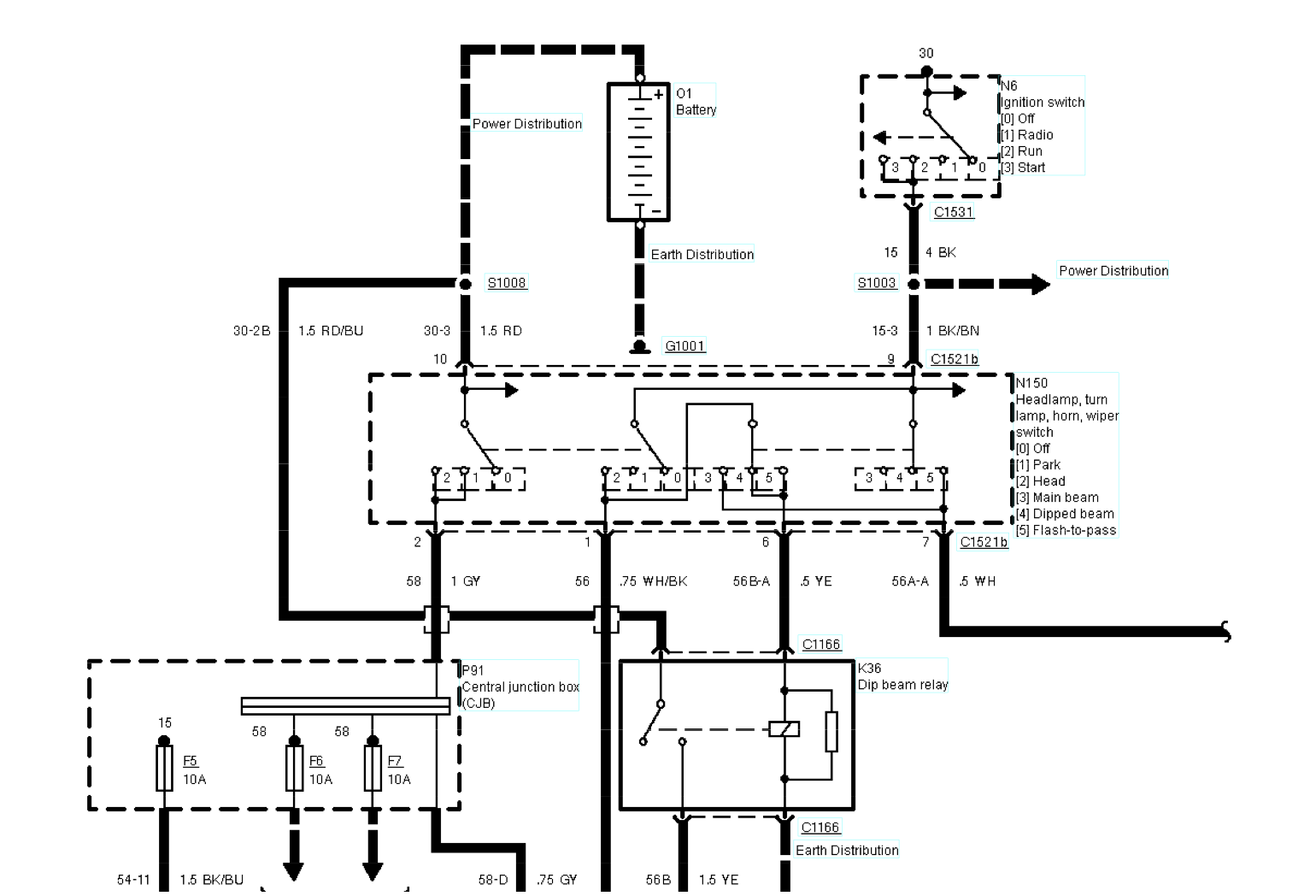
Dip Beam Lamps
With the ignition switch (N6) in run and the headlamp, turn lamp, horn, wiper switch (N150) in position 2 (head), voltage is applied through the switch (N150) and the dip beam relay (K36) to earth. The dip beam relay (K36) energizes, allowing voltage to be applied to fuses 8 and 9 and to the dip beam lamps (E1, E7).
The right dip beam lamp obtains earth through the dim dip relay II (K79).
Main Beam Lamps
The main beam lamps may be illuminated with the headlamp, turn lamp, horn, wiper switch (N150) in position 3 (main beam) or position 5 (flash-to-pass). For both methods, with the ignition in run, voltage is applied through the switch (N150) and to the main beam relay (K37). The main beam relay (K37) energizes, allowing voltage to be applied to fuses 10 and 11 and to the main beam lamps (E1, E7) and to additional headlamps, main beam (E79, E80). With the main beams on, the indicator in the instrument cluster (A70) is illuminated.
Wiring Diagram: (may not display on tablet or phone – Use desktop)
Views: 69