Info
Since day dot of owning ‘The Red Shed’, the exhaust has smelt a bit odd, mainly on startup – enough to give me a headache driving down the road.
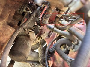
My first thought was perhaps the air filter was blocked however that turned out to be a bit blocked but nothing terrible and was replaced anyway. Next suspect was perhaps a coolant temperature sensor issue – making it think it was running cold. On this 1.1 the coolant temperature sensor is under the inlet manifold. A quick check of the temperature sensor area and I found a wiring issue as detailed below.
Also the fuel gauge has been pretty useless – when filling it up, when down to a quarter on the gauge it would only take 15 or so litres.
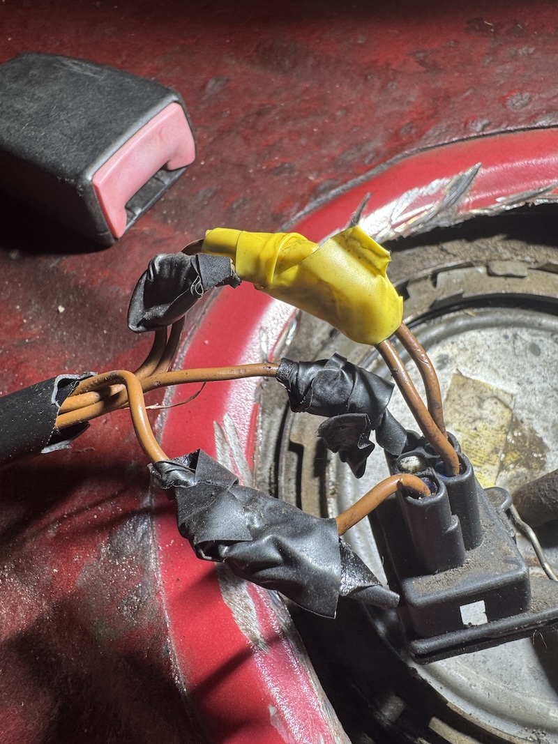
Whilst I was changing the seats over to a set of RS1800 ‘wingback’ fronts / matching rears, a beautiful wiring repair under the rear seats became apparent. They had also cut into the floor, I assume for access to the fuel pump module.
ps. Yes, I had previously purchased some Si wingbacks but after that the RS1800 interior come up – Post on that in the future inc repairing rear seat fabric back onto seat foams.
ECU Coolant Temperature Sensor Wiring / Repair
On inspection of the wiring to the coolant temperature sensor, it had been stretched / routed incorrectly.
Once the plug was removed, the damage was pretty clear and the exposed copper in each wire had been shorting to each other.
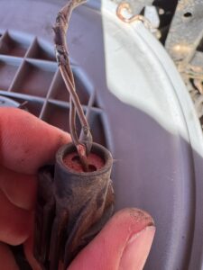
With the wires shorted together, the low resistance could make the ECU interpret the engine as being much hotter than it actually was which would affect fuelling and warm-up/catalyst strategy and so could well make it smell a bit.
Planning to extend the wiring and re-pin, I removed the wires / pins from the connector, the white locking wedge come out OK – but the terminal locking tab inside broke off very easily – to be expected given its age.
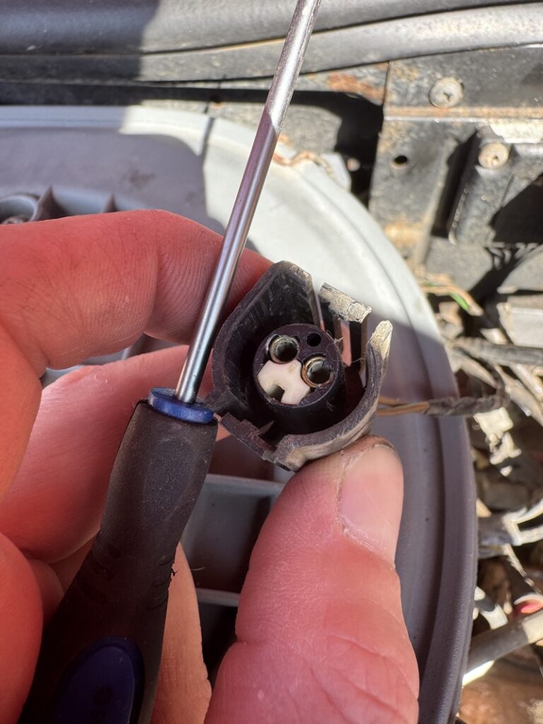
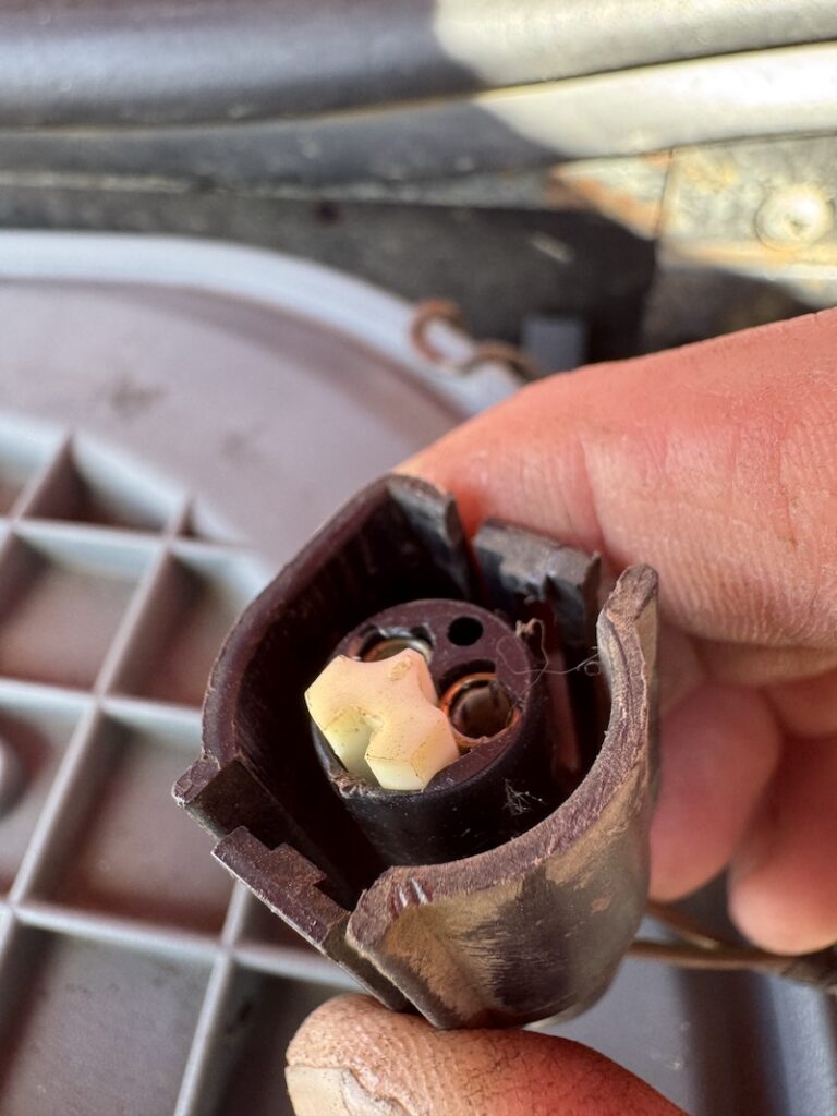
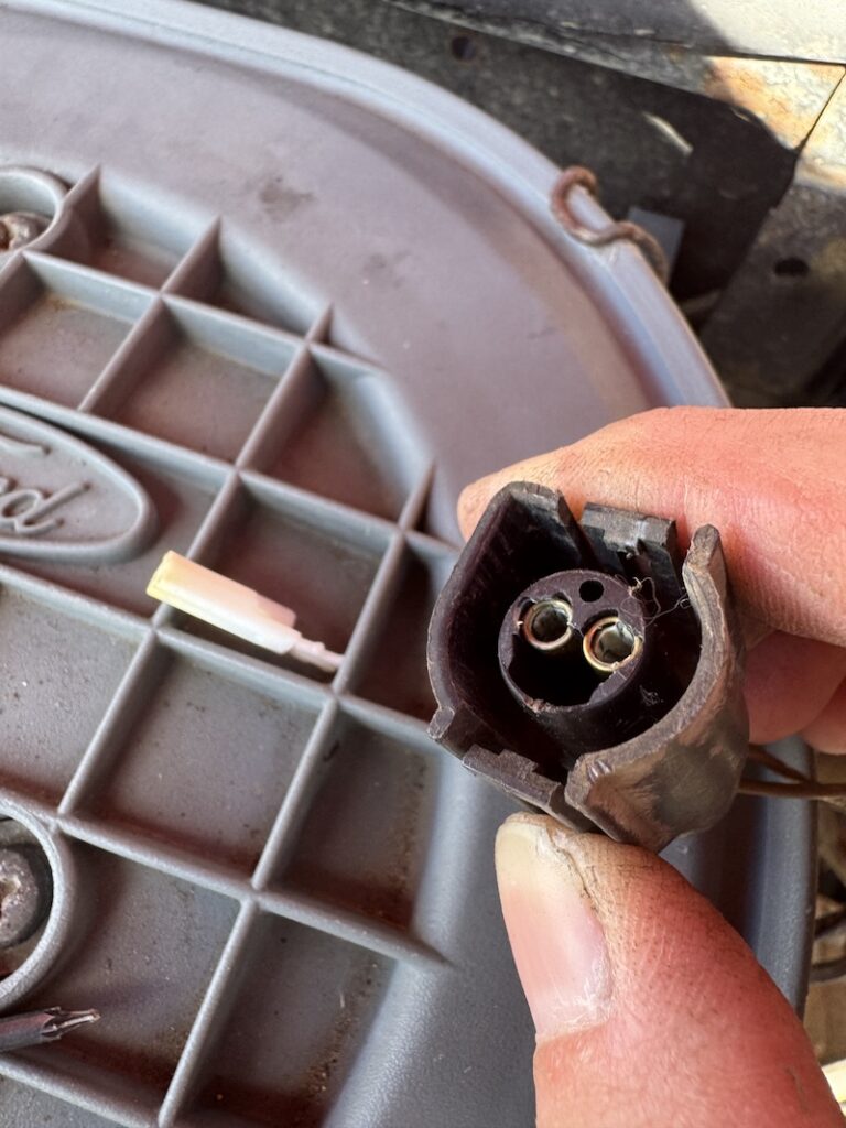
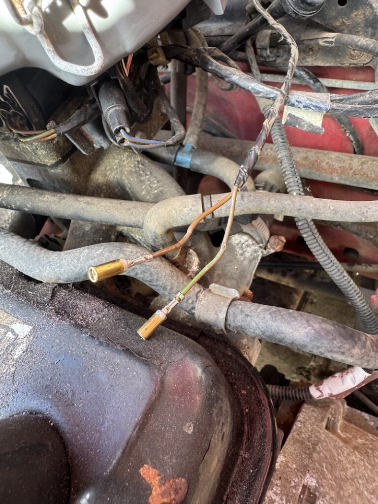
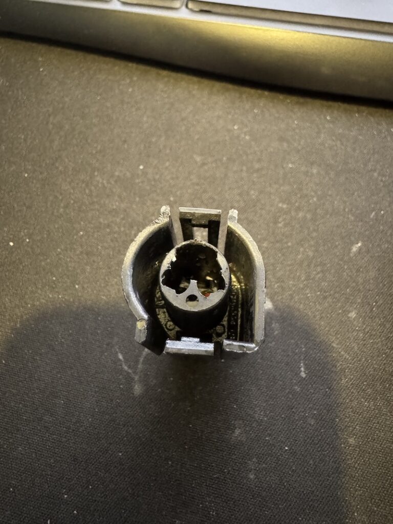
This is where this became testing – trying to get the connector proved not so straight forward.
Inside the connector housing the Ford engineering part number is listed; 89FG-14A464-FBA
After lots of searching I come to the conclusion that it’s probably a TE or Delphi connector. I managed to find various other listings for 14A464 but nothing with the ‘FBA‘.
In particular, the other ‘hand’ seems to be very common and also used Fiesta’ / Escorts’ from this era on the air temp and fan connector.
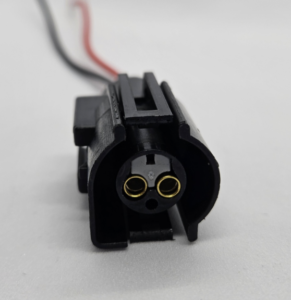
I almost resorted to updating the sensor and plug to the later style used on Mk4/5 Fiestas / Focus / Mondeo etc but was concerned that resistances may be slightly different as they all use EEC-V over EEC-IV ECUs.
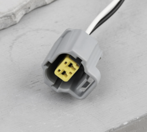
Last resort was Automotive Connector Identification – Facebook Group – great success;
Either from Shop BHP or eBay; Listed as for Granada Cosworth. Number listed against it as ‘LX40’
The wire seals were a little to big for the wiring but I sealed it up with a little silicone for good measure;
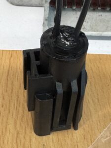
I lacked the ability to take images of the final repair in situ and generally the engine seems to run a bit smoother.
Info – Temp sensor part number / resistance readings
For my little 1996 1.1, the coolant temperature sensor part number is 5263219
If you do need to check the resistance readings of your sensor; I’ve found these readings listed;
| Resistance at 20°C, Ohm: | 37340 |
| Resistance at 60°C, Ohm: | 7548 |
| Resistance at 90°C, Ohm: | 2804 |
This is an NTC sensor. NTC means Negative Temperature Coefficient. As temperature goes up, electrical resistance goes down.
The relationship between temperature and resistance is non-linear, so the resistance doesn’t fall by the same amount for each 10°C increase
You don’t necessarily need to know the exact resistance at every temperature to establish whether the sensor is behaving correctly.
Put a multimeter across the two pins and measure resistance. Then heat the sensor in something like warm water while monitoring the temperature with a separate thermometer.
You should see something like:
20°C 37 kΩ 30°C ↓ 40°C 16 kΩ 50°C ↓ 60°C 7.5 kΩ 70°C ↓ 80°C 3.8 kΩ 90°C 2.8 kΩ
The resistance should smoothly and continuously decrease.
If you get, for example:
20°C 37 kΩ 40°C 16 kΩ 60°C 7.5 kΩ 80°C 3.8 kΩ 90°C 2.8 kΩ
That’s a very healthy-looking NTC.
But if you get:
20°C 37 kΩ 40°C 16 kΩ 60°C 7.5 kΩ 80°C ∞ 90°C ∞
You’ve probably got an open circuit/intermittent sensor.
Or:
20°C 37 kΩ 40°C 16 kΩ 60°C 7.5 kΩ 80°C 7.5 kΩ 90°C 7.5 kΩ
Then the thermistor isn’t responding correctly.
Fuel Pump Module Wiring / Repair
Here’s the top quality repair I found whilst doing the seats;
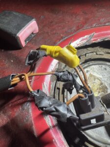
I admire your creativity but come on now! Two wires twisted together and two with exposed copper.
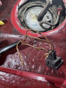
Initially I was going to remove the terminals from the housing, cut the wires back, extend and re-terminate. However on removal of the blue locking tab then releasing the pins from the housing, the tabs broke in the housing.
The Plug part number is 90FG-14A464-GEA. The Ford mould markings include ES88A and 565. It’s a Ford-specified connector housing, rather than a conventional aftermarket connector part number.
It appears to be from the JPT/TE-AMP family of connector systems, although I couldn’t find anything to back this up.
This connector does all of the Fiesta Mk3 fuel pump modules. Probably some escorts too.
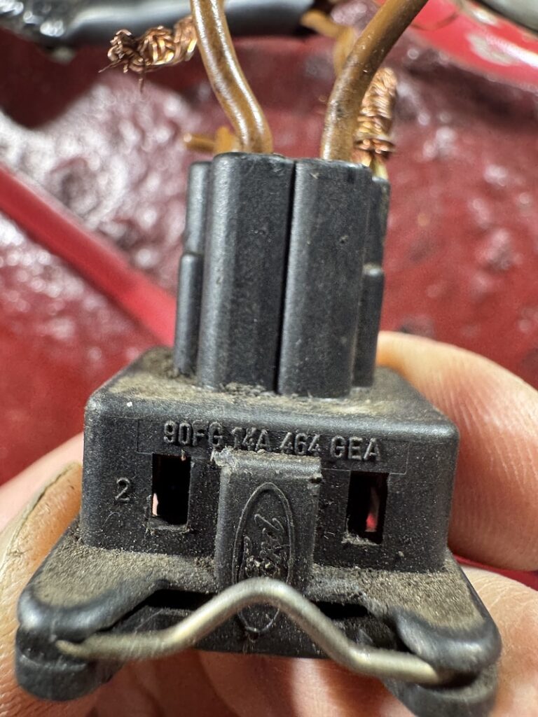
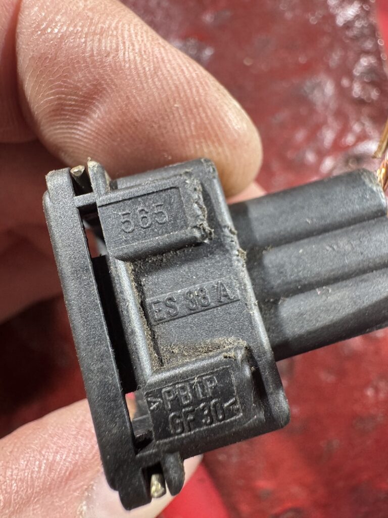
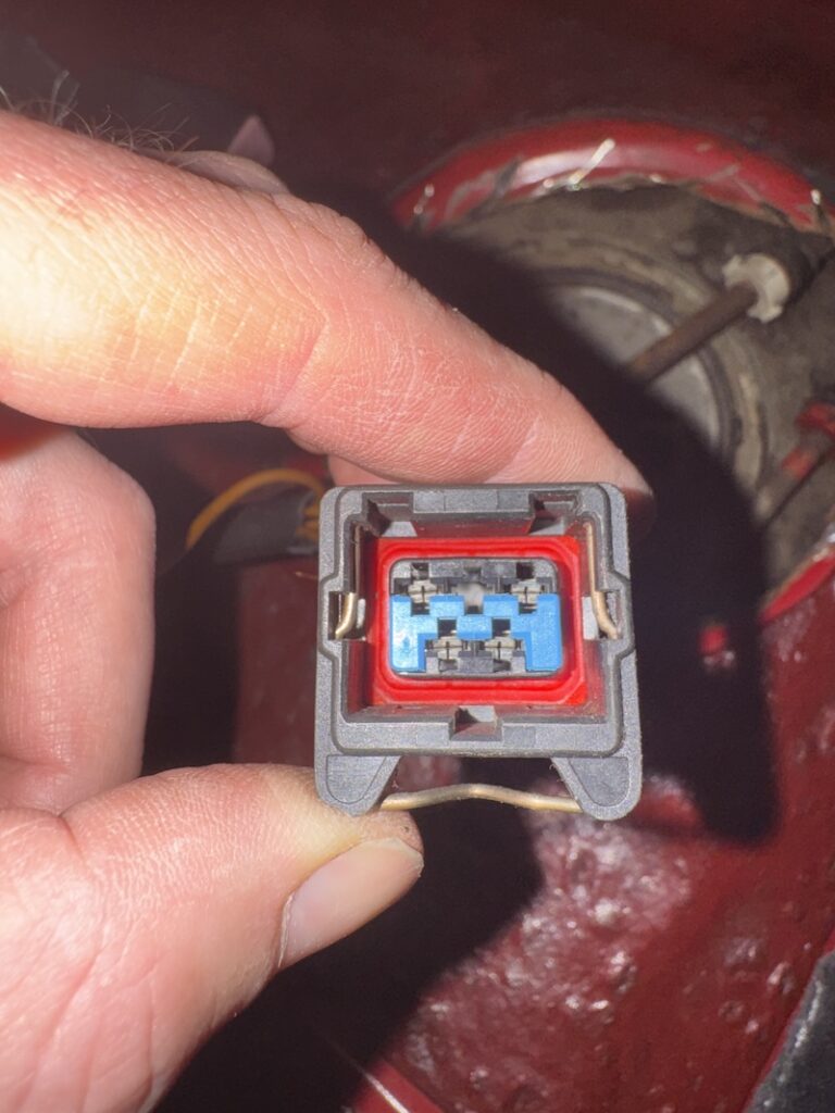
I did manage to find one on ebay again;
In my haste I once again failed to take pictures of the finished wiring repair. The fuel level gauge is working correctly now!
Lastly, I used some duck tape to seal up the opening that has been hacked into the floor. Not ideal by any stretch, maybe one day will repair properly – certainly a job for another day. Its better than the underside of the seat foam being essentially outside
Info – Fuel pump module wiring / pin out
On later vehicles, all the wires are brown for security purposes. Thankfully I was able to extend the wire, terminate and pin the housing wire by wire.
If you’re working with no plug, then Ford wiring diagrams are not the best for this but I could make out the following for the pins;
Pin 1 – Ground for fuel pump
Pin 2 – Not used
Pin 3 – 12v to fuel pump (If PATS fitted, goes to PATs box) (if no PATS probably fuel pump relay) (all via inertia cut off switch where fitted)
Pin 4 – Ground for level sensor
Pin 5 – From instrument cluster / fuel gauge (goes to pin 4 on instrument cluster)
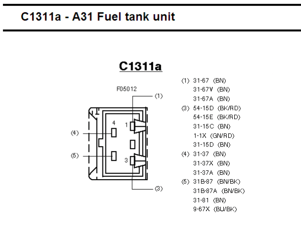
Final thoughts
Two fairly minor jobs that turned into a bit more of a rabbit hole than expected.
The coolant temperature sensor wiring was clearly not helping things, and the fact that the wires had been rubbing together and exposing the copper was probably only going to get worse. Since repairing it, the odd exhaust smell I had noticed since buying the car has gone and the engine generally seems to run a little smoother. Whether the wiring fault was solely responsible for the smell is difficult to prove, but it certainly wasn’t doing the engine any favours.
The fuel pump wiring was a slightly different story. The previous repair was, to put it politely, functional rather than pretty. With the wiring properly repaired, the fuel gauge is now behaving itself, which is another one of those little faults that had simply become accepted as “how the car is”.
It’s also a good reminder with an old car that faults aren’t necessarily going to be caused by the component you first suspect. In both cases the actual components were probably fine; it was the wiring and previous repairs around them that were the problem.
Finding the correct connector housings was probably the most frustrating part of both jobs. Ford’s engineering numbers aren’t particularly useful when you’re trying to buy a replacement 30-year-old connector, and there are plenty of connectors that look almost identical but aren’t quite the right one.
Anyway, both jobs are now ticked off the list. The wiring is considerably less terrifying, the fuel gauge works, the engine smells better, and I’ve got two more examples of questionable previous repairs to add to the growing collection.
The hacked hole in the floor is staying covered with duct tape for now though. Every restoration needs a job for another day.
Views: 6